Touch Toggles are the product of years of testing and research,. Most of the work has been in engineering, making a super-durable stand-alone unit. From the beginning, the effort has been to make the controls universal and adaptable to almost any use. The leads are simply a ground (brown), a 5v DC supply (red), and a “sense” line (yellow); a standard 5v logic level output.
Folks who are handy with modern electronics should have no difficulty using the Toggle’s output for their own purposes. Touch Toggles can directly input to Arduino, Raspberry Pi, and similar microcomputer/micro controller boards. The 1/10″ pin plugs used for our connectors are a standard in the electronics world for most sensor inputs. Touch Toggles are pin compatible and plug right into a common Arduino “Sensor” Shield: Plug them in and read the Toggle’s output. We also offer adapters to the Grove System Arduinos for folks using those type of connectors.
Note: it’s possible, as we mentioned above, to control the indication on the Toggle from an Arduino. The details are listed below.
In the same vein, every base unit designed by Berrett Hill uses that same 5v logic level input. This can be very useful when wanting to control higher energy circuits. Our Snap-Action, Direct, and Direct Plus offer great real-world outputs for logic level controllers.
Note: our Servo Bases back-feed the logic lines during set up, and can not be trivially connected to logic circuits. In this case an inline resistance of 200 ohms or greater will protect the logic lines from passing any damaging currents over 25ma.
In the Model Railroading world, our Universal Translator provides an opto-isolated interface to NCE, Digitrax, and other DCC decoders. This is a very flexible interface base, which outputs 1/2 second push-button closures, and accepts a high/low input that controls the green/red aspect of the Touch Toggle indication. Our Logic Translator offers the same functionality at a lower cost with a 10 pin ribbon cable and direct logic level interface.
We have created a specialized Touch Trigger control for use with Tam Valley Depot equipment. This provides all the function of a Touch Toggle when connected to the standard Tam Valley local control connection.
What’s Inside
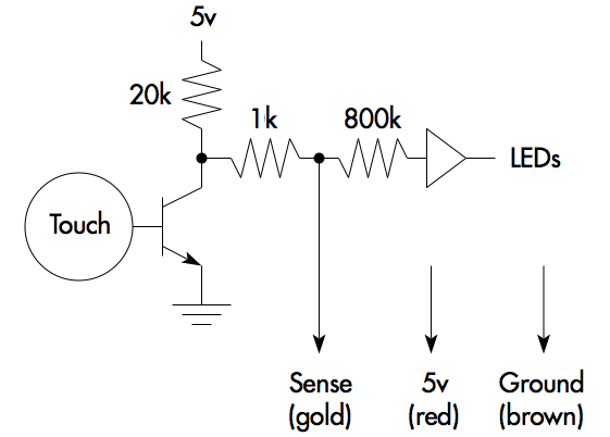
Touch Toggles have their own 20k pull-up resistors and a low internal resistance to work properly with most circuits. The internal 1k resistance is just enough to prevent damage if a “short” is connected through the output transistor.
All of our production toggle controls display green and red or in a special case green and green. All of our Momentary controls display yellow. We produce our own boards on our own equipment, so contact us with any special needs of color or behavior. (The contact numbers are below.)
Almost all of the current used by the Touch Toggle is used to light the LED, so each one draws about 18ma. Each Touch Toggle has an on board voltage regulation circuit so that they are reasonably immune to line noise, but keep the voltage between 4.6v and 5.5v for best results. Don’t exceed these numbers too much or you might let the smoke out.
Finally, here’s the relevant circuit drawing for those that wish to precisely calculate what they’ll see electrically in the circuit. This will work well with any CMOS, and *most TTL logic.
(* TTL pullup resistances less than 5k will overpower the Touch control. For electronics with a higher input signal demand (pullup resistors less than 5k) we offer an Inline Signal Booster. This small device connects between the Touch control and an extension running to a 3-pin input. This active booster passes the signal in both directions and has an sense-line-to-ground resistance of only 200 ohms.)
The following notes are not necessary to use Touch Toggles for on and off input. They are included for advanced users who plan to write code to manipulate the Toggle’s indication:
Controlling the Indication Using Micro Controllers and Arduinos
Touch Toggles are designed to be tri-state devices. Most of the time they are used as an output device, and the internal high/low (green/red) value of the Toggle is simply read and duplicated for the output value of the connected base or powering device. The yellow (sense) wire may be read for this value, while the red wire (5v+), and brown wire (GND) wire provide power.
A close look at the circuit shown above reveals that the sense wire is connected directly to the LED drivers and limited by the 1k resistor from allowing damaging currents to pass through the switching transistor. If the sense line is pulled to ground the indication will be forced to red, and if the sense line is pulled up the indication will be driven to green. The 1k resistance limits the maximum current drained through the Toggle to 5ma.
Obviously the internal state of the touch control cannot be read while the indication is being forced high or low.
The trick to combining controller driven indication and keeping track of the current internal high-low state is to create a loop in the Arduino code that most of the time drives the sense pin to control the indication color, and occasionally sets the pin as an input to read the Toggle output value.
At all times the Toggle holds onto a constant internal value which isn’t affected while the indicators are being over-driven. This value can only be changed by a finger touch. Since the Toggle will alter it’s internal state whenever touched, the Arduino code will need to create a variable to remember the most recent output value for each Toggle. During the sense-loop the current output value must be compared to this last-known-state variable to determine whether there has been a touch. Whenever they are not the same, the last-known-state variable should be updated to equal the current state, and the appropriate response to the touch should be triggered in the code. Note that this response should be tailored to the displayed indication and never to the internal Toggle state, since that value is only known to your code and not to your user.
The time values for this loop are not set in stone, but there are some useful starting points to work with when implementing this. The rule of thumb for how long the loop period can be is 1/5 second or 200ms. This is one of those human reaction standards that comes from extensive lab testing. I’ve tried this, and you can play with this yourself: 1/4 second is a noticeable lag in reaction to a touch, but 1/5 is just below perception.
The second delay to be aware of is that after switching the sense line to an input the code is best to wait for 300us (micro-seconds) for the capacitance and reactance of the sense line to settle out before reading the output of the Toggle. 300us is derived from direct experimentation, and will allow accurate reading of leads of 80 feet or more between the base and Toggle. If all your leads will be much shorter, this time may be shortened. It’s easy to try different values to see what will work for you. The only downside to extending this delay is that in operation whenever the internal value of the Toggle is contrary to the imposed display color, the “dark” LED will flash faintly for this settling duration. Note that if using the values suggested here that flash will be about 1/660 of the time, and therefore should be very faint. In practice you will be able to see this flash when staring straight at a two position Toggle, but it should not be discernible through any diffusion material.
This stuff should hold for all Touch Toggles. When discussing the green over green I usually refer to the “red position” for the light that doesn’t come on at power-up. The green-position is the LED that is closer to the wire attachment point, which is slightly offset where it enters the Toggle case.
I hope this helps. The actual code varies a lot with the type of application. If you come up with a good example I’ll be glad to share it on the site for other users.
Please let us know how you used Touch Toggles, and better yet send pictures!
Kevin Hunter
443 527 6320